
If AIR BAG warning light flashes, count number of flashes to determine DTCs that are set. If AIR BAG warning light does not flash Diagnostic Trouble Codes (DTCs) or flashes DTCs without DLC3 connection, see DTCS NOT DISPLAYED or DTCS CONTINUOUSLY DISPLAYED under 4. If AIR BAG warning light flashes 2 times per second, system is normal (normal code). To check for past codes, connect Diagnosis Check Wire (09843-18040) to terminals Tc and CG of Data Link Connector (DLC3). DLC3 is located under left side of instrument panel. Using Diagnosis Check Wire ( 09843-18040), connect terminals Tc and CG of Data Link Connector (DLC3). To check for present codes, turn ignition switch to ON position. To check for past codes, go to next step.
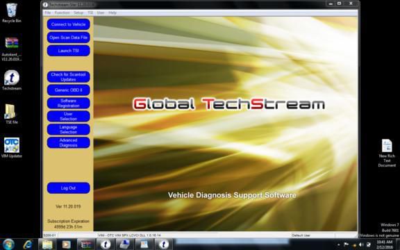
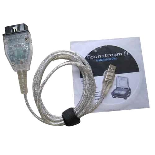
How to toyota diagnostic software code#
DIAGNOSTIC TROUBLE CODE CHART DIAGNOSTIC TROUBLE CODE CHART Center Airbag Sensor Assembly Malfunction Center airbag sensor assembly Front Airbag Sensor RH Circuit Malfunction Front airbag sensor RH Center airbag sensor assembly Front Airbag Sensor LH Circuit Malfunction Front airbag sensor LH Center airbag sensor assembly Side Airbag Sensor RH Circuit Malfunction Side airbag sensor RH Center airbag sensor assembly Side Airbag Sensor LH. If a code is not listed on the display chart, the center airbag sensor assembly may have failed. If the power source voltage returns to normal, the SRS warning light will automatically go off. This malfunction is not stored in the memory by the center airbag sensor assembly. When the SRS warning light remains on and the DTC output is the normal system code, a voltage source drop is likely to occur. If a trouble code is displayed during the DTC check, check the circuit listed for the code in the table below (Proceed to the page listed for that circuit). (See page CA-35) (f) CENTER AIRBAG SENSOR ASSEMBLY The center airbag sensor assembly is connected to the CAN communication system but CAN communication DTCs are not output. If MAIN BODY is not displayed on the BUS CHECK screen on the intelligent tester, proceed to Main Body ECU Communication Stop Mode. The main body ECU is connected to the CAN communication system but CAN communication DTCs are not output. DTC communication uses the CAN communication system. Control Module Communication Bus OFF Control Module Communication Bus OFF DTC communication uses the CAN communication system.
How to toyota diagnostic software how to#
Perform troubleshooting according to HOW TO PROCEED WITH TROUBLESHOOTING (See page CA-9). If CAN communication system DTCs are output, trouble cannot be determined solely from the DTCs. In the CAN communication system, CAN communication system DTCs output by the ECU can be displayed by using the intelligent tester. Each of the front and rear rotors has 48 serrations. These signals are used for control of the ABS system. The speed sensor detects wheel speed and transmits the appropriate signals to the skid control ECU. CAN communication system CAN communication system (Skid control ECU to ECM) CAN communication system (Skid control ECU to yaw rate and acceleration sensor) CAN communication system (Skid control ECU to steering angle sensor) In some cases, the intelligent tester cannot be used when the VSC warning light remains on.

Engine Control System Malfunction Engine control system 4. Control Module Communication Bus OFF CAN communication system CAN communication system (Skid control ECU to yaw rate and acceleration sensor) In some cases, the intelligent tester cannot be used when the ABS warning light remains on. For details of each code, refer to the See page in the DTC chart. If a DTC is displayed during the DTC check, check the circuit indicated by the DTC. Reconnect right-side head impact air bag module connector. If DTC 81-B1162 is displayed, replace air bag sensor assembly. If DTC 81-B1162 is not displayed, go to next step.

Connect jumper wire between Yellow-Violet wire (circuit ICR+) and Yellow-Orange wire (circuit ICR-) of air bag sensor assembly side of right-side head impact air bag module squib harness connector. Reconnect air bag sensor assembly connector A21 (right connector) to air bag sensor assembly.


 0 kommentar(er)
